Andy Norrie
AIC
Add-In Card
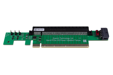
This term is often used to refer to a PCIe slot based device. With the advent of storage devices using NVMe, it is possible plug an SSD directly in to a PCIe slot. In this case the SSD could be described as an ‘AIC drive’. A “CEM Card” is a formal spec term for AIC and stands for Card Electromechanical specification.
Lifewire describes PCIe in more detail.
EDSFF
Enterprise and Datacenter SSD Form Factor
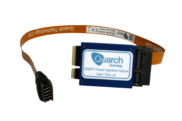
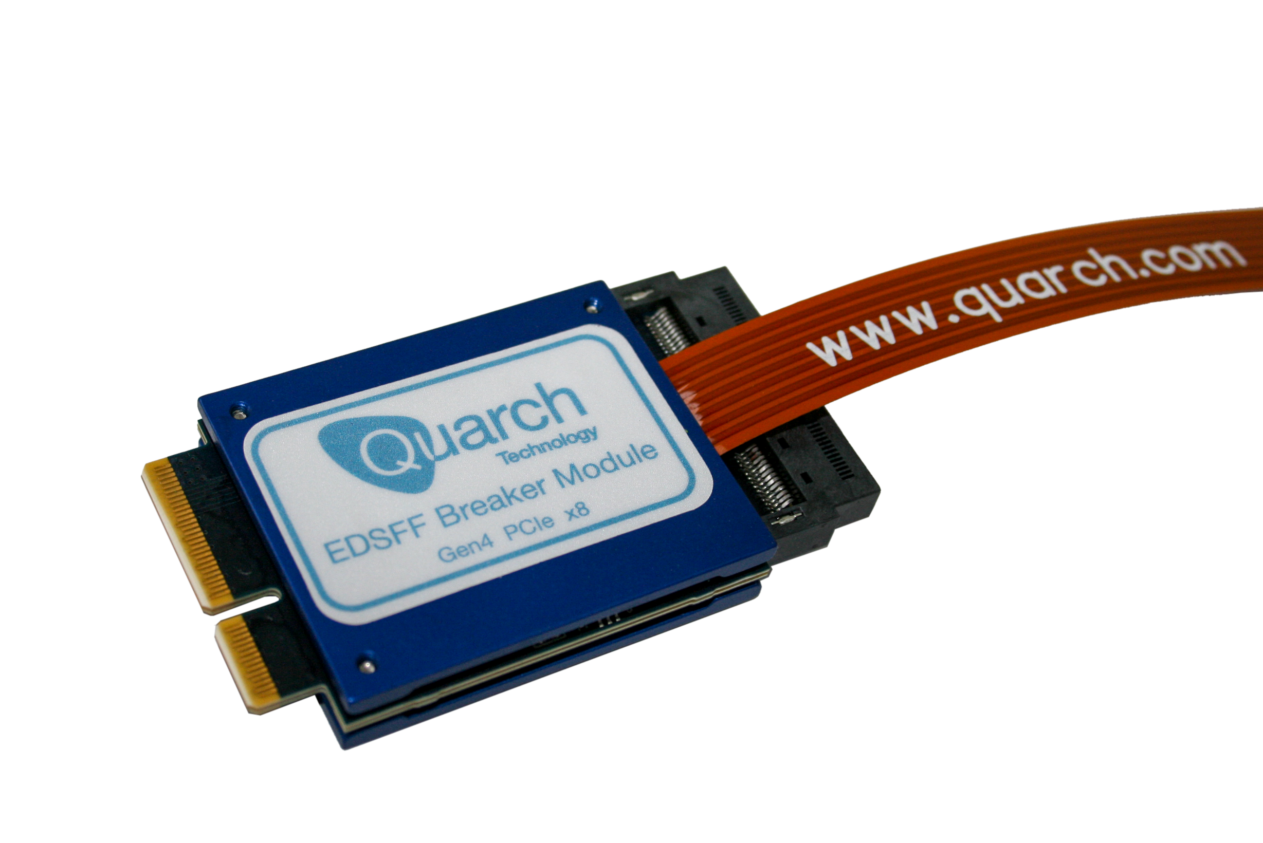
A high density hot-swappable form factor for enterprise storage systems. This comes in several variants, mainly: E1.S and E1.L
Lane widths of x4 and x8 are the most common, though the specification does allow for more than this.
See also: M.3/NGSFF, and Read our blog on EDSFF
E3
EDSFF E3
This builds on the original EDSFF standard and adds another form factor, intended to replace the common U.2/SFF form factor in enterprise storage.
There are currently 4 variants of E3, allowing for different length and thickness of the drives. In addition to storage, the bays could be used for GPUs and similar, with direct interface onto the PCIe bus. Power draw on the largest variant is up to 70 watts.
GenZ
This is a developing specification for the interconnection of storage and processing elements of a computer system. It is designed for low latency and has a lightweight software stack.
How does the Gen-Z fabric improve system efficiency?
AnandTech reports: Gen-Z consortium adds support for PCIe Gen 5
M.2
M.2 is most commonly used for solid-state storage in laptops. They are also found in some enterprise storage systems and consumer motherboards. The interface can be used for either SATA or NVMe-based drives and the connector can be ‘keyed’ to prevent the insertion of some drives.
M.3 / NGSFF
Next Generation Form Factor (originally known as M.3)
This is a competing standard to EDSFF, and is also intended for high density storage using small NVMe drives. It extends from M.2, but appears that it will not be compatible, despite using the same edge connector.
AnandTech’s article – PCI-SIG Warns Of Incompatibilities Between M.2 And Samsung’s NGSFF/NF1
NVMe
Non-Volatile Memory Express
NVMe is a protocol designed for use with solid state disks. It was designed to allow SSDs to be attached to the PCIe bus and make best use of the low latency of flash memory in comparison to spinning drives.
QSFP
Quad Small Form-factor Pluggable
A quad (4 lane) form of the SFP interface, allowing 4 times the data throughput. This is a larger connector that SFP.
PMIC
Power Management Integrated Circuit
A PMIC is the controller used to manage the power supply for an SSD. These can include features such as inrush current limit, power saving modes and (critically) power loss protection (PLP). PLP is required when power is lost and the drive still has data in volatile RAM, which must be stored. High energy capacitors are often used to provide enough power for the drive to shutdown cleanly.
SAS
Serial Attached SCSI
SAS is a very common enterprise storage interface. Normal speeds are from 3G (3 Gigabits/s) to 12G, with 24G speeds now emerging. SAS is used both for connection between a disk and the host and as a back-of-rack cabling interface. Multiple SAS lanes are often used to increase the interface capacity.
Wikipedia: Serial Attached SCSI
SATA
Serial Advanced Technology Attachment
A very common storage interface found on almost all consumer motherboards. SATA is sometimes used for enterprise purposes (when cost is important) but is generally used in slower, less critical consumer devices. SATA devices can be used in SAS systems, though SATA typically only has a single data port.
SFF
Small Form Factor
This is a common term for many technologies. In storage it is generally used to describe the 2.5 inch drive bay standard. SFF drives are one of the most common form factors. They are often also referred to as 2.5 inch drives. U.2 and U.3 drives are further examples of this form factor.
SFP
Small Form-factor Pluggable
The SFP interface is a common, hot-pluggable, network interface. It is commonly used for optical ethernet links, though copper cables can be used. Other protocols can be carried, including Fiber Channel and SONET.
SFF-8639
This is the connector used for U.2 and U.3 2.5 inch (Small Form Factor) storage devices. It was designed for use with SAS, SATA and NVMe drives. Read our blog on SFF-8639
SRIS
Separate Reference Independent Spread
The PCIe device and host use different RefClk sources (Separate Reference), so the clocks may not match each other perfectly, and this must be accounted for. The clocks use spread spectrum clocking, reducing EMI (Electromagnetic Interference).
TrueChip.net explains more about SRIS
SRNS
Separate Reference No Spread
Similar to SRIS, but the clocks do not employ spread spectrum clocking
U.2
This is an interface intended for enterprise-grade solid state storage, and also compatible with hard disks. It is one of the most common ways to attach high-end SSDs.
Read our blog on SFF-8639
U.3
This is a redesign of the U.2 standard, bringing all of the communications standards onto a common set of TxRx pins (unlike U.2 which used different pins for PCIe and SAS). The aim is to have a single drive slot that supports a range of drive types.
For a full explanation, read our blog on U.3


