With big data getting bigger all the time, there’s undoubtedly a growing need for higher-performance data storage solutions. Storage host controllers, specifically, need to be way more reliable under such intensive workloads. Here’s what you need to know about U.3.
U.3 is a ‘Tri-mode’ standard, building on the U.2 spec and using the same SFF-8639 connector. It combines SAS, SATA, and NVMe support into a single controller. Where firmware support is available, U.3 can also support hot-swap between the different drives.
Here’s a hardware engineer’s perspective on how this controller is new, challenging, and full of potential.
Key changes from U.2
Bringing it all together…
With U.2, you’d need a separate connector pinout/backplane, a separate mid-plane, and a controller for each protocol. U.3 only requires 1 backplane, 1 mid-plane, and 1 controller, supporting all these drives in the same slot. This could be a great advantage, with SAS and NVMe forecasted to increase over the coming years and SATA to decrease (according to OpenCompute).
Pinout changes
To configure itself to work with any of the above drives, U.3’s extra pins determine which one is inserted. U.3 has two IfDet pins, whereas U.2 only has one: U.3 needs two to allow for sufficient different combinations to identify the different drives. The host uses different combinations of PRESENT and the two IfDet pins to identify which drive is present.
This brings us to the main difference between U.3 NVMe drives compared to U.2 NVMe drives: the pin-out for the data lanes are different, with all protocols using a common set of data pins. Then there’s the Host Port Type pins (HPT0 and HPT1). The U.3 Gen-Z and U.3 NVMe drives mainly use these pins. Different combinations of these pins tell the drive which host it is inserted into.
U.3 drives are still backward compatible with U.2, though—the U.3 drives determine which host type it is inserted into (by using different combinations of HPT0 and HTP1 being open or ground) and configure the data lanes on power-up. U.3 drives can still act as dual-port NVMe drives in supporting systems.
U.2 drives are not compatible with U.3 hosts.
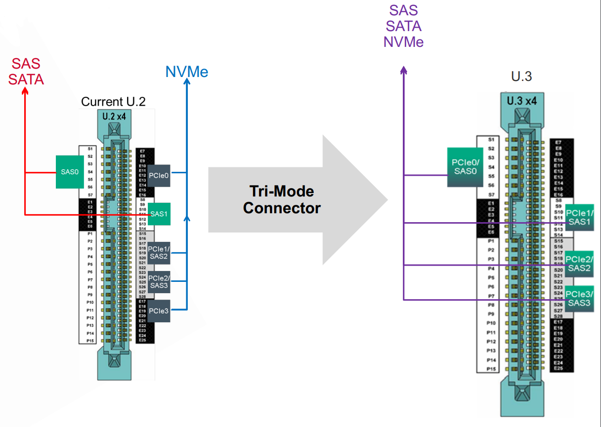
Image © OpenCompute
Challenges still remain—how do we overcome them?
While working with one of the companies leading the way in developing the U.3 host, we encountered a hurdle: compatible NVMe drives for U.3 are difficult to get hold of, with U.3 being so new to the scene. U.2 NVMe drives, unfortunately, don’t work in U.3 because the data lane pin-out doesn’t match. However, SFF-TA-1001 seems to be the key—it sets out what is needed for U.3 drives to work in U.3 while maintaining backward compatibility. Meaning U.3 drives work in both U.2 and U.3.
At Quarch, we’re always adapting, and this is no exception! We worked to develop a small adapter that fits between the U.3 host and a U.2 NVMe drive, allowing the U.2 drive to work in the U.3 host without a problem. This allows hosts to have initial testing performed with existing U.2 drives.
We didn’t stop there. We then added a flexible cable that allows the user to tap into—or break—the SM Bus for testing purposes.
What’s next for U.3?
It’ll be crucial to have reliable testing solutions for U.3 hosts and their compatible devices. Excitingly, I’m closely involved in developing this. We’re now making a U.3 breaker module, that provides full hot-swap automation by allowing all data lines, sideband, and power connections to be connected or disconnected either individually or in groups. It’s also one of the first modules to support external triggering, and it will soon be upgraded to include sideband monitoring!
For me, though, a challenge still remains: while reading the standard, the reader is told to refer to either the PCIe or SAS standards depending on which drive type you’re interested in. The issue here is that the data lanes in PCIe have an impedance of 85 Ohms, while SAS is 100 Ohms. So, when making a U.3 host, which impedance is used?
It’ll be interesting to see, in the future, whether manufacturers counter this problem by changing the impedance of these devices to bring them in line with one another.
U.3 Products are Listed Here!
Read More:
KIOXIA CM6-R Series (2.5-inch) Enterprise NVMe™ Read Intensive SSD
HBA 9500-16i Tri-Mode Storage Adapter

Kyle McRobert