Power Up Your SSDs with an automated test plan
For SSDs and other similar devices, there are common problems that occur, so key tests should be run as early as possible during development. This is a summary of tests recommended by Quarch, which can be easily automated for regression testing.
These tests can be run manually by using the TestMonkey application or a Terminal program to issue commands. Python scripting for automated testing is the recommended approach, however.
Hot-plug
The NVMe promoters group, in association with the UNH-IOL requires a hot-plug test to be run on all U.2 drives as part of qualification. We recommend this as a good starting point.
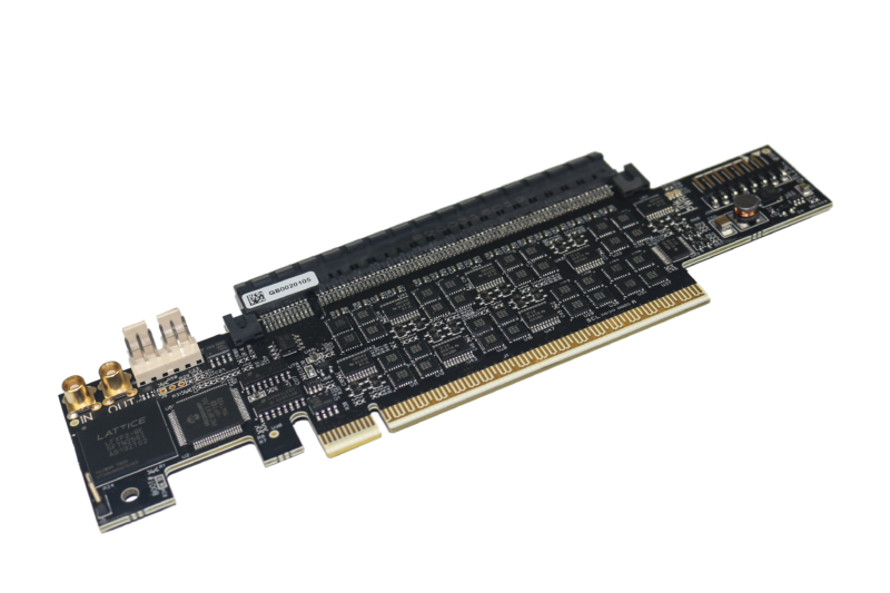
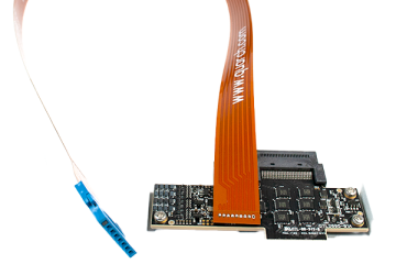
- Place a Quarch breaker module between the DUT and the host
- By default, Quarch breakers connect each pin in the connector based on the pin length, with longer pins mated 25mS after shorter ones. SFF-8639 connectors have 3 pin lengths, so we have a 3 stage hot-plug at 0, 25 and 50mS.
- Command used: config:default state
- This will place the quarch module in its default timing state
- Check you can see the DUT and that it is connected at the expected speed and link width (lspci or SMART tools can be used for this, or internal debug tools).
- We now remove and add the drive 10 times. On each removal, we check the system can see the drive is gone. On each add, we check that the drive is detected AND that the link speed and lane are the same as at the start of the test. While not mandated by the UNH test, you should Ideally also check for any unusual system errors and verify that the drive is accessible (we have seen fails where PCIe connection is good but the NVMe layer is not, so the drive is ‘present’ but not functioning.)Commands used: run:power down and run:power up
Drives are generally expected to be removed within 10 seconds and added within 15 seconds, but the exact timing is not essential. - Now that we have tested hot-plug at ‘normal’ speed, we need to test fast and slow plugs. Repeat the same 10 cycles of remove and add for each of the specified times [25mS, 100mS, 10mS, 500mS]. We are currently setup for 25ms between pin lengths; to change for 100mS, we need to alter the ‘source’ timings of sources 2 and 3. Some breakers may only use 2 sources (as the connector has fewer pin lengths), but changing all 3 will make a test script that works for almost anything (no connector has more than 3 state connection as of March 2023)
Commands: source:2:delay 100 mS and source:3:delay 200 mS
The next power cycle will not run with the new settings (100mS between each pin length)
- If every test cycle completed and the DUT added and removed correctly each time, you have passed the test.
- It would be sensible to go beyond the timings here. It is possible to slam a drive into a bay faster than the 10mS timing, so an additional test at 5mS steps would be sensible, as would a slower one, to simulate a drive that is partly inserted then fully pushed in a second later.
The SSD Review Power Testing – Now Powered by Quarch Technology
Hot-plug with pin-bounce
Pins will not always mate cleanly. While the drive is being pushed in, the pins can move and ‘bounce’ giving an intermittent connection. A simple way to test for pin-bounce failures is to apply pin bounce to each signal in turn (or to those where disruption is likely to cause a failure)
Critical signals for testing on PCIe devices
- Power
- power + precharge (both together)
- PERST
- WAKE
- SMBUS (SMCLK / SMDAT)
- REFCLK
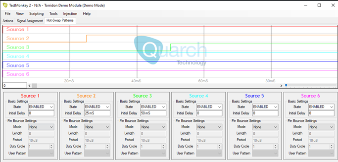
Python can be used to find all the signals on a connected breaker:
AN-020 – Module control with config files – Quarch Technology
Test description
- Iterate for each signal (or set of signals) you want to test
- Start in the default state: Command used: config:default state
- Select an unused source (source 4 is always free on current breakers) and set up a bounce pattern. A pattern with min length of 10mS is recommended and a sensible maximum would be the time that the connector is moving, so for a hot-plug with 2x 25mS steps, 50mS max would be sensible and beyond this would be a more extreme test. We recommend a basic test to use 500uS bounce period and a 50% duty cycle though you can vary this as needed to hit specific timing concerns
Commands:
SOURce:4:BOUNce:LENgth 10 mS
SOURce:4:BOUNce:PERiod 500 uS
SOURce:4:BOUNce:DUTY 50 - Now assign the signal(s) you want to bounce to source 4, command: signal:perst:source 4
- Running a hot-swap with the power down/up commands will now apply this pattern
- After completing the test, make sure you run config:default:state again and repeat the setup commands to set signals for the next test. This is a simple way to ensure each test is setup correctly and no setting from one cycle is added to the next.
- Again, to pass the test, we would expect enumeration, lane width/speed, and drive access to work every time.
Hot-plug with signal delay
This is another extension to the hot-plug test. The aim here is to take key signals (or all signals) in turn and connect them before/after the time they would normally mate. We are looking for corner cases where unusual timings may cause a failure to enumerate (or even a crash). The most critical signals to test will be the same as with the pin-bounce test above.
Test description
- Iterate for each signal (or set of signals) you want to test
- Start in the default state: Command used: config:default state
- Setup the standard sources, increasing the delay on them, so we have the time for an earlier connection. For this example, we are adding 100mS to the standard times
Commands:
signal:1:delay 100 mS
signal:2:delay 125 mS
signal:3:delay 150 mS - Select an unused source (source 4 is always free on current breakers). We will assign the signals under test to this source and alter its delay time to create the sequenceBy setting the delay to less that 100mS, we will connect the chosen signals early. Setting between 100mS and 150mS will connect during the plug and setting more than 150mS will connect after the main plug sequence.Suggested timing:
0mS – Connection prior to main plug
50mS – Connection just prior to main plug
100mS – Connection aligned with start of plug
125mS – Connection aligned with middle of plug
150mS – Connection aligned with end of plug
250mS – Connection just after the plug
1000mS – Connection well after the plugCommand:
SOURce:4:BOUNce:LENgth 0 mS - Use the power down/up command to cycle the drive with the new timings. A single cycle at each speed is a good start, though multiple cycles would be better and will significantly increase the test time
- Again, to pass the test, we would expect enumeration, lane width/speed, and drive access to work every time.
PCIe lane width reduction
This simple test aims to ensure that device enumeration will work correctly with all lane widths.
Test description
- Start in the default state: Command used: config:default state
- Verify the device lane width and speed and operation is as expected
- Power down the device, command: run:power down
- Now change the lane width. Most Quarch modules have a specific command for this:
Commands:
config:width 16
config:width 8
config:width 4
…
Older modules that do not support the width command may be possible to upgrade. If not, you can still control the width be disabling the specific lanes, command:
signal:lane1:source 0
Setting signal(s) to source 0 will prevent them from ever connecting - Power up the device, command: run:power up
- Again to pass the test, we would expect enumeration and lane width/speed and drive access to work every time.
Error injection test
In this test we use the ‘glitch’ function to briefly interrupt one or more signals. The main targets will be data lanes and critical sidebands (SMBUS, refclk) that have the highest risk of causing a critical failure.
Test description
- Start in the default state: Command used: config:default state
- Verify the device lane width, speed and operation are as expected
- Iterate through each signal(s) you want to interrupt. Enable glitch on the signal(s), command:
Here we enable glitch on both the Tx and Rx pairs of Lane_0 (4 signals in all)
signal:lane0:glitch:enable on - Now we set the glitch length, 50nS is the smallest available time. command:
glitch:setup 50nS 1
Glitch length is comprised of a time value and a counter (50nS x 1 = 50nS). Other time values are available to create a wide range of glitches (see command: help glitch) - We can either create a single glitch with the command: run:glitch once
or we can use the PRBS generator to create a random sequence with the command: glitch:prbs 65536
PRBS values are in a power of 2 ratio from 1:2 (50% glitch time) to 1:65535 (0.0015% glitch time) - Begin the sequence with the command: run:glitch prbs
- Check that the link is still up and the device is operable
- End the glitch sequence with: run:glitch stop
- Verify the device is still up and working fully
- You may wish to read and log the physical layer error counters if you have access to them
- Increase the length of the glitch and/or the PRBS ratio to create more errors. Ideally, increase until the link actually fails. As we are faulting Lane 0, we would expect access to the device to fail at this point. The key test will be, did it fail ‘nicely’, or were additional errors/crash seen?
- As SMBUS interruption is a known cause of crashes, glitching these signals would be another sensible test to run.

Andy Norrie