What is a PMIC
Why your SSD died: exploring the PMIC. SSDs can seem very robust in comparison to spinning drives, but surviving a drop is not the only risk to your data. An SSD is a complex device, and there are a whole host of failure points to be aware of.
Today I want to take you through the PMIC (Power Management IC) and if supported, the PLP (Power Loss Protection) backup mechanism. Please keep in mind that PMICs can vary quite a bit. Based on the form factor and target market (client, embedded, datacenter, and enterprise). For precise PMIC details, please consult the component manufacturer or SSD manufacturer. We are presenting you with a simplified discussion of the PMIC.
There is a lot of SSD design information below, so feel free to skip ahead to the ‘Testing’ sections if you want!
SSDs, as you know, are quite complex systems that must translate IO transactions from high-speed host interfaces such as PCI Express and buffer these IO transactions. Then perform write or read cycles to non-volatile memory such as NAND. The power delivery subsystem of an SSD is also quite complex, so we’ll discuss some test scenarios with regards to this subsystem in this blog.
SSD design
Typical SSDs employ a power management IC also known as a PMIC to convert host voltage from the connector into several smaller regulated voltages to be used by the various components on the SSD (note: voltage regulation can also be accomplished with discrete components, so not all SSDs will employ a PMIC).
PMIC is an acronym that is not unique to SSDs, and you will find that vendors that manufacture PMICs for SSDs will also have similar products for laptops, cell phones, or other embedded control. A typical list of components found on the SSD’s PCB besides the PMIC is:
- the main controller is sometimes known as the SoC (system on a chip)
- DDR RAM, used as a write or read buffer and tracks logical to physical LBA
- Non-volatile memory is usually in the form of NAND flash.
Voltage regulation
All of these components require their own set of core and IO voltages and the PMIC will use the main host voltage coming from the respective host connector and will use individual low-dropout (LDO) regulators or switching mode power supplies (SMPS) depending on the current demands. Furthermore, the timing sequence of when these component voltages are powered up or powered down may require exact timing in order to ensure proper state behaviour.
Monitoring
If the default timing sequence is insufficient, an internal I2C bus could be employed with the SoC/firmware instructions sent to the PMIC to assist in the timing control. (It should be mentioned that the I2C bus may also provide real-time voltage and current data, as well as flag over-current and under-voltage conditions. Some PMICs may also offer a thermal diode for ambient temperature monitoring, though the location of the PMIC may not indicate the maximum temperature of the SSD).
Power loss
If the SSD supports inadvertent or unsafe power removal, power loss protection (PLP) capacitors and boost regulators may be part of the power delivery subsystem.
If the PMIC detects an unsafe power removal, not only will the reserve backup energy of the PLP capacitors take over, but an interrupt will also be sent to the SoC, It will notify it that power loss is imminent and to take steps to abort future host transactions, complete any current NAND transactions, and save off any critical firmware context.
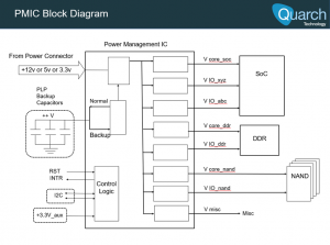
The concept shown in the block diagram above ‘Figure 1’ PLP circuit is that when in normal mode, a large bank of capacitors (size and quantity are determined by the amount of time in mS required by firmware to accomplish unsafe housekeeping) are charged up by a boost regulator within a range of 25 – 35V (manufacturer-specific).
When the host voltage, let’s use +12V as an example, drops below some set threshold, say 11.0V for a given amount of time, then the PMIC’s internal logic makes the decision to allow the PLP circuit to kick in. The device bypasses the voltage from the power connector and taps into the energy that the charged PLP capacitors provide. In addition to this, the PMIC will typically send an interrupt to the SoC to notify the SoC of the unsafe power loss and prepare for shutdown.
To be clear, the energy supplied by the PLP capacitors typically limits to tens of milliseconds. The SSD’s firmware must be extremely efficient to handle this disruption without risking data loss.
Testing a PMIC
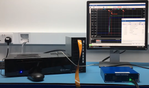
A simple power loss test configuration might employ a switch to disconnect power to the SSD. I did this test with our Programmable Power Module (PPM). It’s very quick to set up and extremely powerful in what it can test.
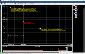
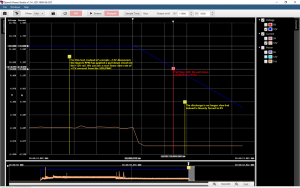
Below, in Figure 3, we can see such a scenario where +12V is disconnected and the voltage eventually bleeds to near 0V. This is captured in Quarch Power Studio (QPS) where we can annotate the trace for later review.
The fall time from +12V to +9V is about 208uS and we presume the logic has switched to PLP backup at this point, as the current drawn is approaching 0.
Testing more cases
But what if power is not simply disconnected and allowed to leak down to 0V? There are server power supplies that employ a discharge circuit in order to meet certain power-down sequences for their given designs. The most aggressive test is the ‘crowbar’ test where the rail is shorted to ground (imagine that a screw or similar metal component shorted the power rail).
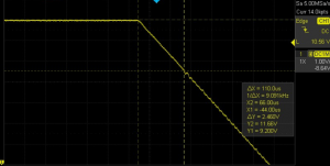
In this type of scenario, the +12V rail is rapidly forced to 0V. The Quarch programmable power module (PPM) has an optional pull-down mode that can mimic almost any rate of voltage drop. Please see the Quarch QPS capture in Figure 4 and for correlation purposes, the exact same capture on scope in Figure 5.
In this situation, +12V down to +9V we roughly doubled the rails fall rate to about 112us. In this case, we used a simple pull-down pattern to the slope that is similar all the way from 12v to 0v. More complex patterns could be used to simulate almost any possible scenario.
This case gives the PMIC’s internal logic even less time to react to an unsafe event. If the PMIC’s logic fails to react to this scenario, the all-important interrupt to the SoC may not be issued. Therefore, the SSD firmware could be unaware of the catastrophic event that has just taken place.
Testing with Quarch
The Quarch Programmable Power Module or PPM as some of you know, acts as the power supply to the target SSD, much in the way a power analyzer would act as the source.
The PPM allows for fine control of the host voltage, including the use of complex patterns. This can be done in our software or scripted easily in Python.
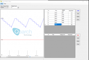
As shown in the example below, a validation engineer could develop a test to characterize the PLP trip point of the PMIC by stepping down from +12V in small or large steps.
Validation engineers can quickly develop tests of the SSD’s power delivery system. Since the PPM acts as the supply to the SSD, voltages such as the +12V rail can easily be set for + or – V margin limits. Power can be quickly cut in back-to-back scenarios to test the recharging of the PLP capacitors. Or the replay robustness of the firmware.
Also, recall that the PMIC is responsible for providing many regulated voltages to the various components on the SSD. Margining the main +12 or +5V or +3.3V from the host connector is desirable. The test possibilities are many if the engineers are given the proper tools and development time.
The Growing Importance Of PMIC Validation

Lee Hayashida