PCIe 5.0: What you need to know and how you can test Gen5 devices
We’ve been working on a lot of exciting new things this year, including a set of test fixtures for PCIe Generation 5 storage devices. PCIe Gen5 aims to support the mainstream increase of data-heavy technologies such as cloud computing, 5G, and AI. Here you’ll learn about what makes it different from its predecessor and what we’re doing to help test its robustness.
What’s new with Generation 5 PCIe compared to Generation 4?
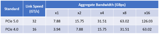
Simply put, PCIe 5.0 (or ‘Gen 5’) doubles the data transfer speed compared to PCIe 4.0, making it robust enough to handle new data-heavy tech. The PCIe 5.0 standard is essentially an extension to PCIe 4.0. The new transfer speed follows the previous trend, doubling to 32 Giga Transfers per Second (GT/s) compared to 16 GT/s on PCIe 4.0.
32 GT/s is the raw speed (how many bits can be transferred per second); the data rate is slightly slower than this, as the data rate takes into account the bits used for encoding the signal. The bandwidth of the link is the data rate multiplied by the width (physical PCIe links can be 1, 2, 4, 8, 16, or 32 lanes wide) and is usually expressed in the form PCIe x1, PCIe x2, etc.). Below is a table showing the bandwidth of PCIe 5.0 compared to PCIe 4.0, taking the encoding bits into account:
So, we know the main point of PCIe 5.0 is to double the data rate compared to the previous generation, but what does this mean for implementing the protocol? PCIe 5.0 has a few changes to allow for the faster speed but remains backward compatible with PCIe 1.1 to 4.0, both electrically and mechanically. Some of these changes include:
- Increased loss budget – The loss budget is now -36dB (compared to -28 dB on PCIe 4.0), this is needed because as the signal frequency increases, the amount of resistance experienced increases. The loss budget refers to the insertion loss; this is the amount of power the signal losses when it’s transmitted from A to B.
- New CEM (Card Electromechanical Specification) Connector Definition: This only allows for pad connectors. Through-hole connectors are no longer allowed, as these usually have much higher losses and crosstalk issues (crosstalk is when one signal causes undesired effects on another signal).
- A post-equalization minimum eye height of 15mV and a minimum eye width of 9.375pS (0.3UI): The eye diagram is used primarily to look at digital signals for the purpose of recognising the effects of distortion and finding its source. Basically, eye diagrams are used to measure how good the signal quality is, so if the eye diagram is outwith this specification, the receiver will struggle to read the data correctly.
- New jitter Limits – Jitter is short time variations from its ideal position.
What support does Quarch have for Gen 5?
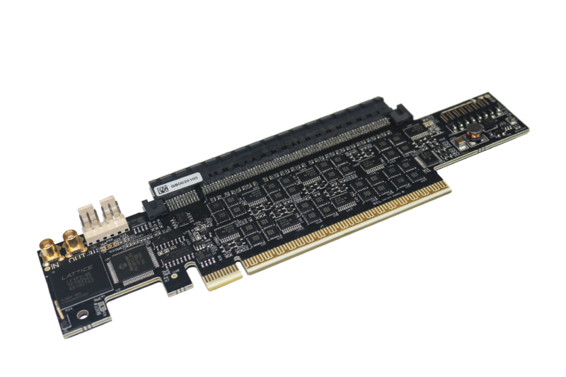
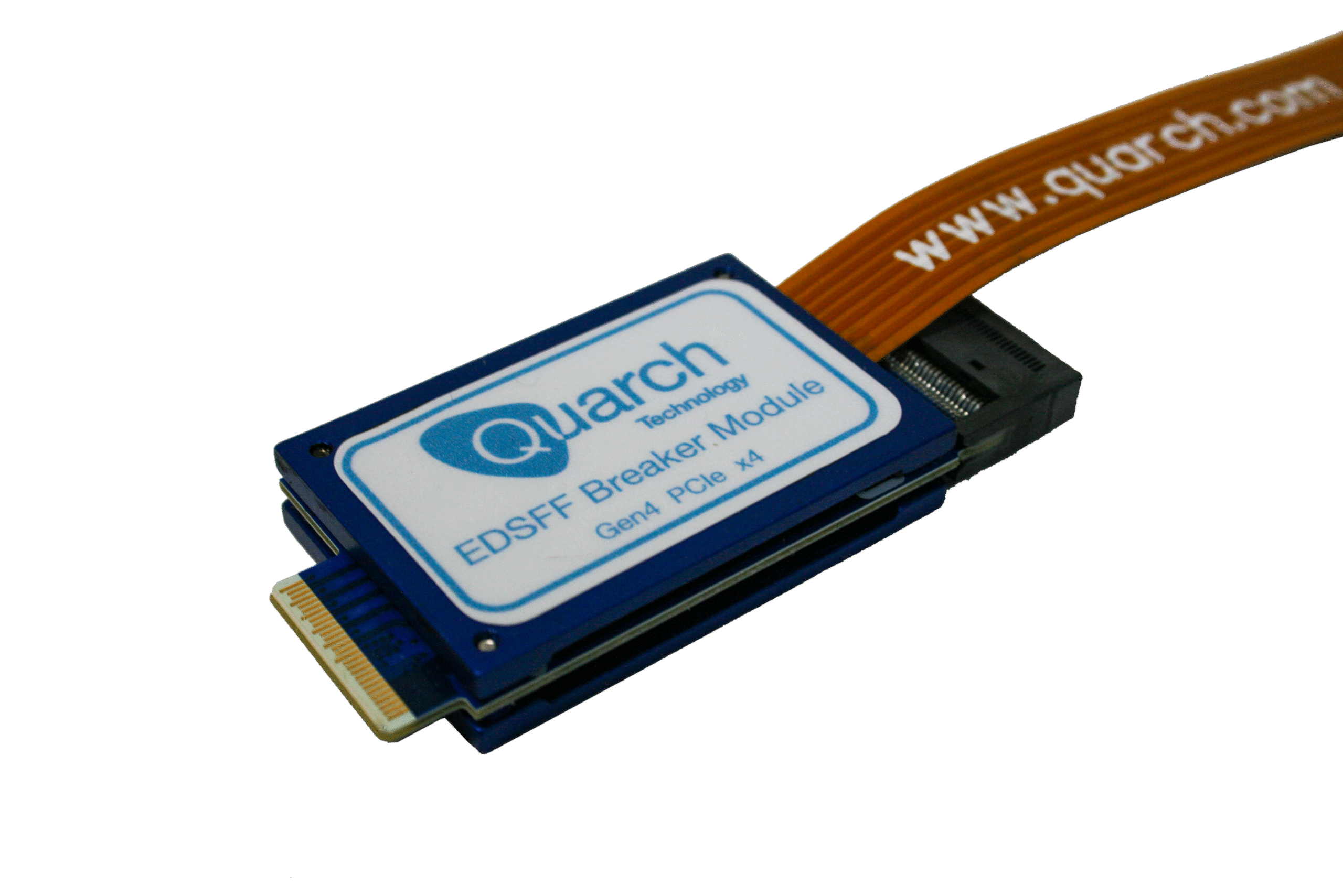
Quarch has recently released our first Generation 5 PCIe breaker modules, to be used in PCIe x16 AIC (add-in card) systems, and we have 3 variants:
- QTL2357 – Gen 5 PCIe x16 Breaker Module
- QTL2358 – Gen 5 PCIe x16 Breaker Module with triggering
- QTL2396 – Gen 5 PCIe x16 Breaker Module with current inrush
More breakers and power analysis fixtures are being released each year, so sign up for our newsletter to stay updated!
These breakers are like our Gen 4 breakers, but we have redesigned the module to work at Gen 5 speeds, along with adding some new features. To allow our modules to operate at these increased speeds, we have added new components for switching, new connectors rated for PCIe 5.0, and an improved PCB design to help reduce crosstalk (which we believe will be more of an issue compared to losses as data speeds continue to increase in systems).
Here are the features you can expect in the new modules:
- Independent control of every signal, including each side of differential pairs
- Programmable control over connection timing and pin bounce
- They allow power injection from an external source
- Active driving of CLKREQ, PERST, PWRBRK and WAKE signals. This allows the user to drive the signal, allowing for a wider range of testing options
- NEW Sideband monitoring commands: These commands allow you to find out the state of selected sidebands (High or Low)
- External triggering in and out to allow syncing with other modules and devices (QTL2358 only).
- Trigger events off of host power (12V, 3V3 and 3V3 Aux) (QTL2358 only).
- NEW Sideband over trigger (QTL2358 only): This allows the user to output sideband signals through the triggering connectors in real time. An example of this is outputting SMB data and clock signals, allowing the user to connect these to a SMBus analyser or oscilloscope when debugging SMBus protocol issues or NVMe MI problems.
- Inrush current limit (QTL2396 only). This limits the inrush current to the device.
Don’t forget to sign up for updates to know about new module releases for Gen5 as soon as they happen.
References
- https://www.rambus.com/blogs/pci-express-5-vs-4/
- PCI Express Gen 5 Specification & latest information of Gen 4 testing – Internet Infrastructure, CSG – Rick Eads
- PCI Express Base Specification Revision 5.0, Version 0.3

Kyle McRobert